

A reliable people counter installation starts with the right sensor, coverage plan, and validation. This guide focuses on overhead, network-connected counters: check the model’s mounting requirements, provide compatible power and data, and compare its results with a manual count before using the reports.
Poor placement, unsuitable equipment, configuration errors, and network problems can all affect results. Check both the count at the device and the data reaching the dashboard before using them for staffing or conversion-rate decisions.
The four steps below cover sizing, placement, cabling and mounting, and configuration and testing. Confirm who is responsible for each part before installation day.
What to settle before you start
Before you buy or drill, know which sensor type you are installing, what your network must provide, and what the whole job costs. Confirm these with the installer and IT team before work begins.
How a people counter works and which type fits
Many overhead counters detect people crossing a virtual count line or counting area and record direction. Other designs use beams at the doorway. Compare specific models and their test conditions rather than assigning one accuracy percentage to an entire technology.
| Technology | How it detects | What to verify | Site check |
|---|---|---|---|
| Infrared break-beam | A beam interrupted at the doorframe | Direction sensing and treatment of simultaneous crossings | Test people walking side by side |
| Thermal | Heat signatures from above | Operating temperature and supported mounting range | Check nearby heat sources against the model’s guidance |
| Stereo video (3D) | Two lenses capture depth | Coverage, lighting requirements, and calibration | Test crowding, obstructions, and changing light |
Ask the supplier to demonstrate performance under your expected traffic conditions. A technology label or an “AI” feature alone does not establish suitability.
Tools, network, and budget checklist
Gather these before the install day:
- Ceiling height and ceiling type (drop tile, drywall, concrete, exposed steel)
- Appropriate access equipment and trained personnel for work at height
- Drill, anchors rated for your ceiling, level, tape measure
- Cat5e or Cat6 cable, a crimper or punch-down tool, and a cable tester
- A compatible PoE switch or injector for PoE-powered models
- A laptop to run the sensor’s setup tool
- An IT contact to confirm addressing, network access, and security requirements
Request an itemized quote covering sensors, mounts, power equipment, cabling, software or licenses, installation, and support. Confirm recurring fees and any separate configuration or validation work.
Evaluate the system during busy traffic as well as quiet periods.
Step 1. Work out how many counters you need
Sensor quantity depends on the model’s supported coverage at the actual mounting height, the opening’s width, and the traffic path. Do not assume one sensor covers every standard doorway.
Measure the opening and the ceiling
Measure the clear opening and mounting height, then use the selected model’s coverage chart or design tool. For example, Axis lists a maximum counting width of 3.06 m at a 3 m mounting height for the P8815-2. That is a model-specific example, not a rule for other counters.
Measure the ceiling at the exact spot where the sensor will go. Soffits, beams, and bulkheads can change both the mounting height and the clear view.
Map the entrances and define the measurement
For whole-area occupancy, account for every entrance and exit. For customer traffic, define how staff movements and repeat visits will be handled. Passage counts are not automatically counts of unique shoppers.
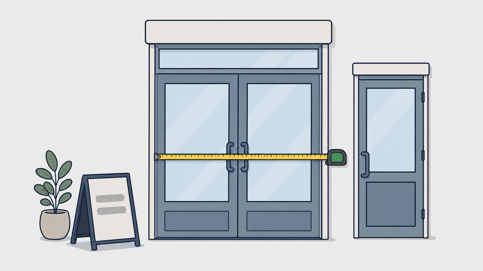
Use a site worksheet like this hypothetical example. Opening width alone is not enough to order sensors:
| Entrance | Width | Coverage decision |
|---|---|---|
| Front double door | 6 ft | Check one-device coverage at the measured mounting height |
| Mall frontage | 40 ft | Use the manufacturer’s multi-device design and calibration guidance |
| Staff entrance | 3 ft | Confirm coverage and whether staff traffic belongs in the report |
| Total | Confirm after the coverage design |
Finalize the equipment quantity and installation quote only after confirming coverage and reporting requirements.
Use model-specific coverage, not a fixed sensor-per-door or sensor-per-foot rule.
Step 2. Choose and mark the mounting spot
For a top-down counter, follow the manufacturer’s mounting orientation and height limits. Position the counting area over the traffic path, clear of obstructions. Other counter designs may require a different orientation.
Center the sensor over the traffic path
Place the counting line or area across the full walking path. For wide entrances, use a supported multi-device layout and calibrate its shared coverage. Overlapping images alone do not prevent gaps or double counting.
Check the bracket alignment and the live counting area using the model’s setup procedure.
Avoid the spots that cause false counts
The best location is not always the geometric center. Walk the entrance during a busy hour and look for these problems:
- Door swing and closers. A moving door in the field of view can read as a person.
- Hanging signs, banners, and displays. Moving displays can obstruct the view or interfere with detection.
- Strong sunlight through glass doors. Check the model’s tolerance of glare, shadows, and changing light.
- Lingering zones. Queues and people lingering in the counting area can complicate tracking.
- Heat sources. Check placement near vents and heaters against the thermal sensor’s instructions.
Adjust the location within the model’s placement limits, then recheck the full counting area.
Mark the spot and test the view before drilling
Use a safe, secure temporary mounting arrangement and the setup view to confirm usable coverage before drilling. Check the mounting surface and concealed services, then mark the approved fixing points.
Confirm the live view before you drill, because moving a mounted sensor means patching the ceiling.
Step 3. Run the cable and mount the sensor
For a compatible PoE counter, one Ethernet cable carries power and data from the switch or injector. Follow the selected device’s instructions for cabling, mounting, and startup.
Power and data over one PoE cable
Match the device’s required PoE standard and power class, not just its stated wattage. Cisco’s PoE reference distinguishes 802.3af and 802.3at and highlights power negotiation and switch-budget checks. The source-port rating is not the power guaranteed at the device after cable losses.
Use compliant cabling specified for the installation. A standard copper Ethernet channel is limited to 100 m (328 ft), including patch cords; a typical structured-cabling design allows 90 m for the permanent link. Longer routes need a separately designed solution.
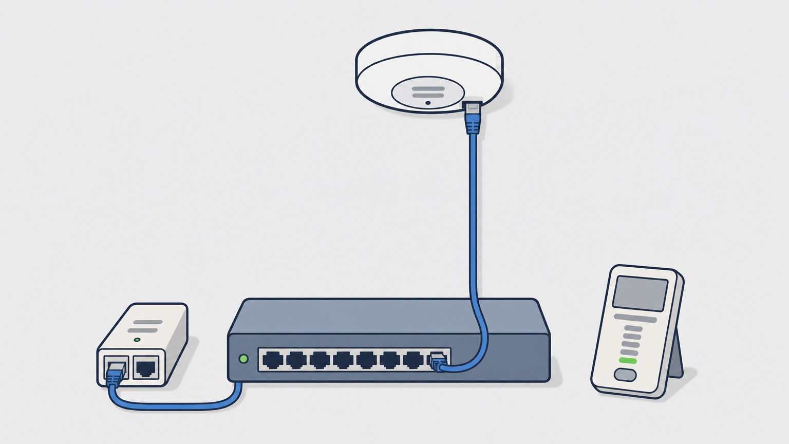
Plan the route from the network closet to the entrance before you pull anything. The longest runs and the hardest ceilings decide how long the job takes.
Pull, terminate, and mount in order
Follow this sequence:
- Pull the cable along your planned route, leaving appropriate, supported service slack.
- Terminate both ends and test the run with a cable tester.
- Label both ends with the entrance name, such as "Front Door Sensor."
- Install the bracket with anchors rated for your ceiling type. For suspended ceilings, use the manufacturer-approved mounting and support arrangement.
- Attach the sensor in the specified orientation and check its coverage.
- Plug in and watch for the link and power lights.
Label as you go. Six months later, someone will need to trace which cable belongs to which entrance.
When to bring in a technician
High ceilings, restricted access, and complex cable routes may need specialist planning and access equipment. Discuss low voltage structured cabling with MegaServices and confirm the scope, required qualifications, site access, and availability before booking.
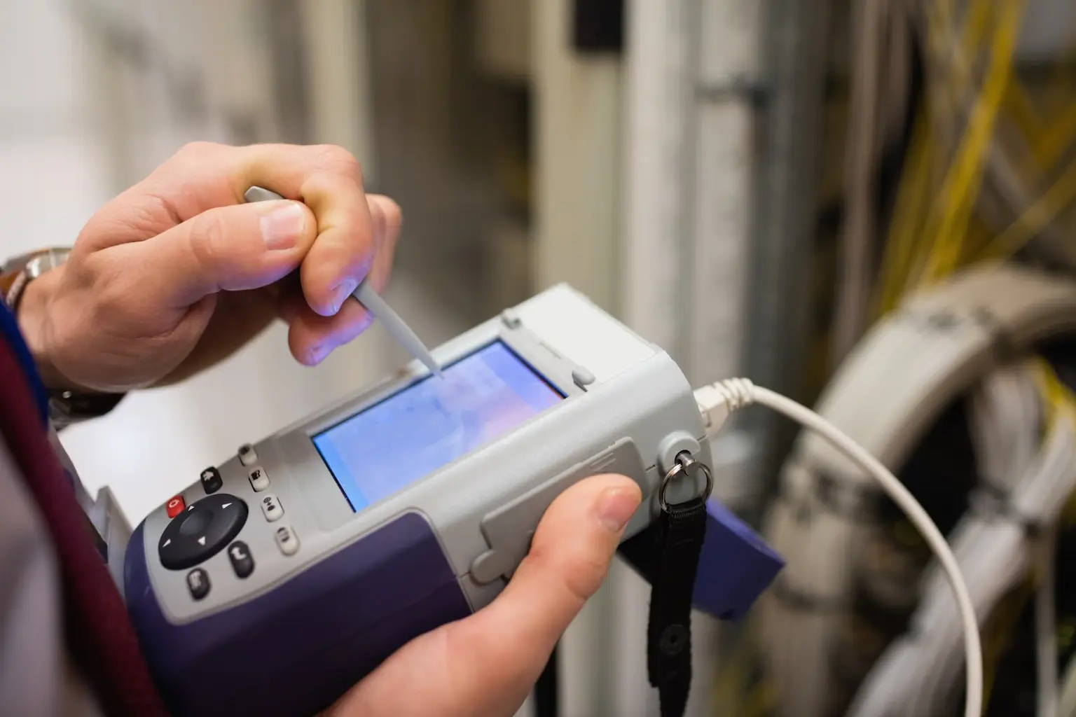
Test the cable and mounting as well as the counting performance.
Step 4. Configure and test for accurate counts
Connect the sensor to your network, set its mounting height and count line, then compare its output to a manual tally. Confirm that the reporting platform receives the same time-aligned results.
Connect, name, and calibrate
Have IT confirm addressing, time synchronization, and the manufacturer’s required network connections. A DHCP reservation can keep an address consistent; it does not guarantee connectivity. Avoid blanket firewall changes or exposing the device to the internet. Once it is online, work through this setup list:
- Name each sensor after its entrance.
- Enter the mounting height using the manufacturer’s measurement reference.
- Configure the counting line or area across the walking path.
- Set which direction counts as "in."
- Synchronize the time and set the correct time zone and counting schedule.
- Adjust or mask interfering areas only as supported, without excluding legitimate crossings.
Validate against a manual count
Compare manual and sensor counts over the same time window, separately for each direction. Test busy and quiet conditions, groups, carts, and relevant door positions. Follow the supplier’s validation method and agreed acceptance criteria; a short quiet test may contain too few passages. AXIS People Counter’s validation procedure, for example, calls for at least 100 manually counted passages.
Record the entrance, time window, manual and sensor totals for each direction, and any missed or double-counted crossings. Use this simple discrepancy check when the manual count is greater than zero:
Absolute count discrepancy (%) = |sensor count − manual count| ÷ manual count × 100. If the manual count is zero, report any false counts instead of dividing by zero.
If the manual total is 200 and the sensor reports 191, the discrepancy is 4.5%. This is not the same as per-person detection accuracy: missed and extra counts can cancel out. Review individual crossings where the system supports it. If results fail the agreed test, troubleshoot the sensor and repeat validation.
Fix common problems
| Symptom | Possible cause | Fix |
|---|---|---|
| Undercounts groups | Coverage, mounting, calibration, or crowding | Check the model’s placement limits and calibration |
| Overcounts | Door swing, sway, reflections | Review placement and supported zone settings |
| In and out reversed | Direction setting | Flip the direction in setup |
| No data in the dashboard | Power, addressing, connectivity, or reporting configuration | Check device counts first, then have IT trace data delivery |
Re-run your manual check after any remodel, lighting change, or new signage near the entrance.
Complete handover only after the system meets the agreed validation criteria.
Get the first count right
A good people counter installation comes down to four decisions made in order: how many sensors the entrances need, where each one mounts, how the cable and bracket go in, and whether the counts survive a manual check. Document the configuration and test results so later changes can be checked.
Need help with the physical installation? Discuss cabling and mounting with a MegaTech™. Confirm the project scope and who will configure, validate, and support the counting system.
Mega Has The Staffing Solutions You Need For Your Next Pro AV Project.
Let MegaServices help you grow your business by providing you with the qualified personnel you need when you need them.
John Pierce III is the Director of IT at Mega Services, connecting the company’s people, processes, and technology. Drawing on experience in field installation, technician support, recruiting, and dispatching, he develops systems, automations, and reports that make work simpler and more efficient. John specializes in identifying inefficiencies and transforming complex processes into practical, user-friendly solutions.
